Dædalus
For the core of Dædalus we used an Aurel's 433.92MHZ AM transmitter. This transmitter matched the emitter in the Icarus/Wally module. There's nothing special about these modules - they filled our requirements: they used allowed frequency and power and they fit in our budget.
The idea is very simple: Dædalus receives the data from Icarus and it's driven into a RS232 port. A computer does all the smart work: decoding and validating the message. Although in the greek mythology Dædalus was pretty smart, our Dædalus is very dumb. Forgive us. If it eases your pain and/or makes you happy, Dædalus only works if a computer is attached, so you can call "Dædalus" to the set "box + computer". This way you can think Dædalus is smart. However we call Dædalus to the box.
The only thing smart about Dædalus is the fact that it can give us an idea of how far Wally is from us. That is achieved by using a pin in Aurel's receiver that is proportional to strength of the received electromagnetic signal. By using a very low pass filter we can get the average of the power of the signal; so all we need to do is feed this into a multimeter and calibrate. At this stage you don't need the computer anymore, so Dædalus is dumb again. Sorry!
The hardware
This is probably the most important part of Dædalus. Here is the schematic of Dædalus:
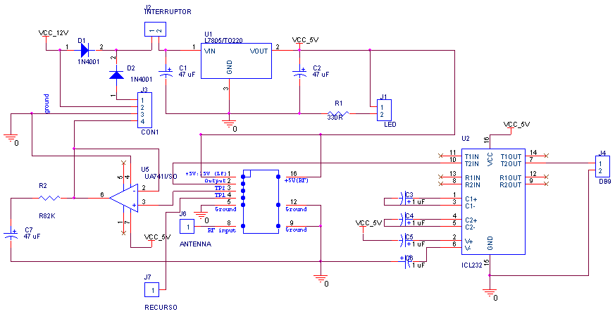
and this is how it looks like after mounting:
Power supply As you could see, the approach is simple. For the
power supply, we wanted to use 9V batteries or our own 12 V power supply. That's
why we've put two generic diodes (1N4001) before the switch. This way, the
batteries would only be used if there was no external power supply. This way,
when we were looking for Wally we could plug Dædalus to the car's lighter; if
we had to walk out of the car, Dædalus would survive!
The whole of electronics in Dædalus needs 5V, so we used a standard voltage
regulator. We also used a LED to remind us that Dædalus was on or off (the
resistor in the schematic just limits the current: I = V / R ).
TTL <-> RS232 conversion The 433.92 MHz receiver has a pin that is TTL compatible, so we used the standard MAX232 (actually, we used a ICL232, but it is just an alias from another manufacturer) to convert TTL logic to RS232 logic. The herd of capacitors this semiconductor uses were chosen accordingly to MAX232 datasheet. It was very simple.
Range finding Although Aurel's documentation was lousy, we
empirically found out that one pin's output was proportional to the antenna
signal. We decided to use this feature to find out how far Icarus/Wally would be
from us (by using a omnidirectional antenna). When looking for Wally, this
would also allow us to move freely, without the bother of carrying the
laptop computer because all we needed was the directional antenna, Dædalus and
a multimeter.
The philosophy was again very simple: by using a generic ampop (LM741) in a
voltage-follower setup, we isolated the signal so that we could apply a low pass
filter. We did not know if the receiver would go crazy in case the RC filter
sucked up a lot of current: the voltage-follower has a high input impedance, so
it would solve our problem. The idea of using a low pass filter is quite dumb
actually, because we just use it to extract the average voltage.
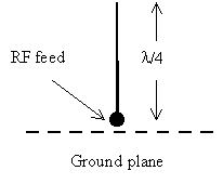
The antennae
Dædalus had two antennae coupled to it, although not simultaneously. When
Icarus is in the air, we use a quarter of wavelength antenna; when we are
looking for Wally, we use a Yagi antenna.
After spending quite a lot of time looking for the right antennae to use, once
we realised we needed two antennae - an omnidirectional and a directional
- we ended up choosing the quarter of wavelenght antenna and a Yagi antenna.
For the quarter of wavelenght antenna, we inspired in Aurel's own antennae and
in all the antennae design handbooks we could find. It is indeed very simple: a
piece of wire ![]() m=17.28
cm long (keep in mind that
m=17.28
cm long (keep in mind that ![]() (in
meters)) and a ground plane. The ground plane acts as a mirror so the whole set
is theoretically equivalent to a dipole.
(in
meters)) and a ground plane. The ground plane acts as a mirror so the whole set
is theoretically equivalent to a dipole.
 |
 |
|
Quarter of wavelenght antenna |
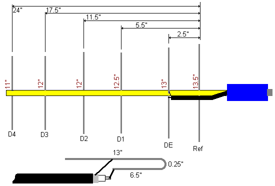
Yagi antenna (scheme taken from http://www.tfs.net/~petek/RDF/70ant.html ) |
For the Yagi antenna we followed thoroughly an excelent tutorial
in http://www.tfs.net/~petek/RDF/70ant.html
. We used alluminium instead of brass, but now we regret it: we couldn't solder
the alluminium properly, we had to scratch the rod, solder the wires minimally
and apply epoxy to give rigidity.
The physical support
Dædalus was built in a normal housewife translucid plastic box (similar to Tupperware) we got in a cake promotion. Everybody we know laughed about this but it was very pratical: it was easy to drill holes in it and the lid allowed easy access to the inside.
The software
We used two pieces of software: Windows's Hyperterminal and our own "Dædalus
Operator". Hyperterminal was useful to find out how much garbage Dædalus
was picking up, so it was our low-level tool.
"Dædalus Operator" is a Visual Basic 6 application that does
basically the same as Hyperterminal but isolates the messages and validates
them; we used it to collect the data.
At first we were transmitting at 8 data bits with no parity, and we were picking
up a lot of garbage. We then decided to use 7 data bits with even parity:
jackpot! Half our comm problems were gone.